
Chris Howe looks at the construction methods being used for the structures that will carry HS2 to the West Midlands.
Construction of the 220km (140-mile) HS2 route between London and the West Midlands involves building 50 “significant” viaducts and 175 other bridge structures, crossing roads, existing railways, waterways and other natural features.
Some of the viaducts will be engineering marvels in their own right, such as the 3.4km (two-mile) Colne Valley Viaduct. Others, designed to blend into the landscape, will be modest in comparison.
Given that so many bridges and viaducts are being constructed, it’s not surprising that some will share the same or similar construction techniques. However, some structures require a more bespoke solution for delivery.
It would have been ideal to use a standardised method of construction across the whole of the route.
However, the construction methods for each structure had to be based on several factors. Those include length and height, but the space available for construction, ground conditions, and the nearby infrastructure also played a part in deciding the design for each viaduct.
In addition, the Department for Transport specified that each structure must be designed to last 120 years without requiring significant maintenance.
Many of the viaducts have also been designed to withstand immense lateral forces. For example, the viaducts on the main line have been designed to resist the force imparted if full braking was applied as a 400-metre-long train travelling at up to 360kph (225mph) was on or approaching the viaduct.
So, while using standardised methods would be preferable, it is not always possible to create just one or two viaduct designs that would meet all of the criteria.
That’s not to say that the contractors delivering HS2 haven’t tried to use as much standardisation as possible - indeed, many of the viaducts share the same engineering principles.
One technique which has almost universally been adopted is the use of as much off-site construction as possible, to manufacture structural elements in a controlled environment.
Delta Junction
Delta Junction is being built to the east of Birmingham. It will comprise a series of viaducts which will form a three-way grade-separated junction in a Delta shape (from which it gets its name).
Because of the scale of the junction (and its location), several techniques are being employed to construct a number of viaducts across the sprawling site.
Some methods are more straightforward than others, such as that used to construct the River Colne viaducts on the southern section of the junction.
Two 160-metre-long spans were constructed, using steel beams which were lifted into place by crane onto pre-built concrete piers. Installation of the beams was completed in December 2024, after which the process of lifting precast concrete deck segments and parapets began.
Although several construction methods are being employed across the site, the scale of the junction has allowed the Balfour Beatty VINCI joint venture (BBV JV) to use a standard method for the vast majority of the viaduct spans.
Nine of the viaducts will be constructed using precast concrete deck segments - much like the Colne Valley Viaduct, although the assembly method used differs somewhat.
But although the Delta junction site as a whole is enormous, in some cases the individual site locations for the viaducts are constrained.
The Water Orton Viaduct, for example, must cross the busy M6 Toll/M42 interchange, which is 11 lanes wide.
Meanwhile, the River Tame Viaduct, which is sandwiched between the M6 Toll/M42 Interchange and the sprawling Hams Hall Distribution Park, must also cross the River Tame.
The challenging conditions mean that the viaducts, while sharing the same segmental design, are being assembled using three distinct construction methods.
The segments for 153 individual spans are being assembled off-site at a purpose-built facility established on the outskirts of Marston (Sutton Coldfield). The Kingsbury site (as it is known) will be used to manufacture 2,742 concrete segments, each weighing between 50 and 80 tonnes.
The main method being used to assemble 136 of 153 individual spans is broadly similar to the launching girder method used for the Colne Valley Viaduct, although the cantilever system works differently.
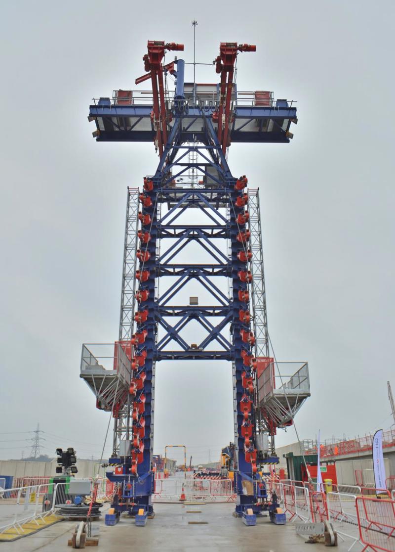
The cantilever method utilises a temporary deck erection system, which during construction produces a structure that resembles a cable-stayed bridge.
The system uses a temporary steel tower installed above one of the pre-built piers. Stay cables are then attached to a previously constructed deck span, while further stay cables on the other side of the tower are attached to concrete segments for the next span as they are installed.
A swivel crane lifts each segment, swivels it into position, and holds it in place while temporary steel bars are installed within the segment.
Once the steel bars are in place, the stay cables are attached and the segment can be released from the swivel crane. The crane is then moved into position on top of the segment which has just been installed.
The segments are transported to the crane from a holding area and across the previously assembled deck using an SPMT (self-propelled modular transporter).
Owing to the number of spans being assembled using this method, BBV JV ordered four temporary deck erection systems which were designed and manufactured by BERD.
This is not the first time that a bridge has been constructed using a cantilever method in the UK, but it is the first time that this particular system has been used to construct a viaduct in Britain.
The majority of spans will be constructed using this method, although 11 spans must first be constructed using a ‘side span’ method.
This utilises a temporary steel truss which is placed between two piers and used to support the segments during assembly. It is used to construct each initial viaduct span, as the cantilever method requires a completed span to which stay cables are attached.
A further six spans will be pre-assembled and then moved into position using SPMTs.
This method will involve fully assembling and post-tensioning the spans close to the viaduct site. The spans will then be moved into position above the M6 Toll/M42 Interchange during a series of weekend-long closures, which are due to take place in mid-2026.
The reason for using pre-assembly is to reduce disruption to a key motorway interchange. While it may have been technically feasible to use the side-span or cantilever method, this would involve working above the motorway for extended periods, which is best avoided.
Despite using three different methods to assemble the 153 spans, they will all share the same structural design - which means the deck sections will all take the form of hollow post-tensioned concrete box girders.
Colne Valley Viaduct
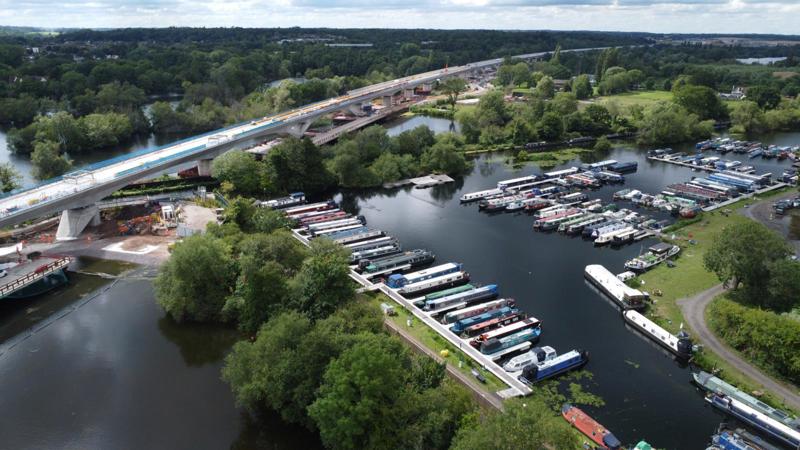
In the case of the Colne Valley Viaduct, engineers had to determine how to build “the UK’s longest bridge” over a series of lakes, waterways and roads, all while keeping local disruption to a minimum.
The viaduct is being constructed by the Align Joint Venture (comprising Bouygues Travaux Publics, Sir Robert McAlpine and VolkerFitzpatrick), which is delivering the HS2 section between the northern Northolt Tunnel portal and northern Chiltern Tunnel portal.
Owing to the unique geopgraphy and design of the viaduct and the surroundings, it was decided to utilise a bridge-building leviathan imported from Hong Kong. The launching girder, christened Dominique, was used to build the East Tsing Yi Viaduct, which was constructed by Bouygues Travaux Publics in 2008.
The 160-metre-long, 700-tonne launch girder was used to lift 1,000 precast concrete segments into place, each weighing between 60 and 140 tonnes. As each bridge span was completed, Dominique was able to move to the next span to begin construction once again.
The segments were manufactured close to the northern abutment at a purpose-built factory in West Hyde. Assembly of the viaduct began in 2022 and the final segment was lowered into place in September 2024 - an incredible achievement.
The Colne Valley Viaduct is a landmark structure and is noticeably larger in scale than most of the viaducts along the route. But despite its sheer size, the viaduct almost looks grateful, thanks to the design which was intended to mimic a stone skipping across water.
Wendover and Small Dean Viaducts
At only three metres high, the Thame Valley Viaduct is a relatively low structure, which meant that it was relatively straightforward to assemble the viaduct in situ using cranes.
The deck for the Wendover Dean Viaduct in Buckinghamshire, however, is 14 metres off the ground at its tallest point. It would therefore have been difficult to utilise cranes to move large bridge sections into position.
For this reason, the viaduct was constructed using a method known as a deck slide - otherwise known as a ‘push launch’.
This method quite literally involves pushing the bridge deck out onto pre-built piers. It meant the deck could be assembled in a single location, rather than having to reposition cranes as construction progressed.
The nearby Small Dean Viaduct, which is 345 metres long, was also constructed using the same method.
In this instance, however, the deck slide was utilised in part to keep disruption to the busy A413 and Chiltern Main Line to a minimum. Both had to close for a period of time during the slide, which took place in February.
The Wendover Dean Viaduct deck was pushed into position over three separate slides, with sections of the deck assembled before each launch.
The 4,320-tonne deck for the Small Dean Viaduct on the other hand was pushed into position in one movement, to reduce disruption to the main road and railway.
The Wendover and Small Dean Viaducts are just two of five viaducts which are being delivered using the same structural design and construction technique.
They are being delivered by the EKFB Joint Venture (formed of Eiffage, Kier, Ferrovial Construction and BAM Nuttall), which is constructing the central section of HS2 between the Chiltern Tunnel and Long Itchington Wood.
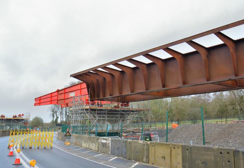
The large steel beams for the viaducts were manufactured by Eiffage Metal in France. They were transported to the UK by ferry, before being delivered to site by road.
The decks have been constructed using a double composite construction method which involves placing precast concrete panels at the top and bottom of the steel beams. The top and bottom panels are then covered with a layer of in-situ poured concrete.
This produces a hollow deck which is relatively lightweight but is also incredibly strong.
Thame Valley Viaduct
While many of the viaducts on the route are more modest in scale, construction is no less challenging.
For example, a floodplain to the west of Aylesbury posed a unique challenge which drove engineers to use as much pre-fabrication as possible - so much prefabrication, in fact, that construction of Thame Valley Viaduct is thought to be a UK first.
Because the viaduct has to cross through a flood plain, there is little space to construct the deck, and a lot of preparation was required before assembly of the viaduct could begin.
First, a haul road had to be constructed, as well as pads used to support cranes. The temporary road, which had to be constructed above the height of the floodwater, also had to be built in such a way that it did not contaminate nor block the flow of water.
Completion of the haul road enabled workers to assemble the bridge piers and deck relatively quickly. Assembly of the deck structure began in November 2023, and since then all of the main precast bridge elements have been installed. Work is now focused on pouring the final layer of concrete to permanently stitch the precast deck elements together.
Each span was constructed using 25-metre-long, 100-tonne bridge beams manufactured by PACADAR on The Isle of Grain.
The beams were transported to the site by road and lifted into place using two crawler cranes. They were then topped with bridge deck sections, which were also manufactured off-site.
It is the use of prefabrication for the bridge piers, beams and deck which makes this a UK first.
Curzon No.3 Viaduct
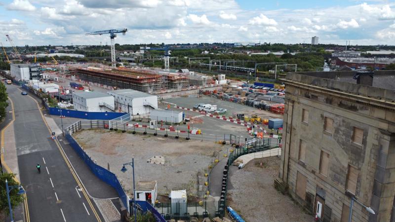
Heading towards Birmingham, a series of bridges and viaducts will bring trains into the city from Bromford Tunnel.
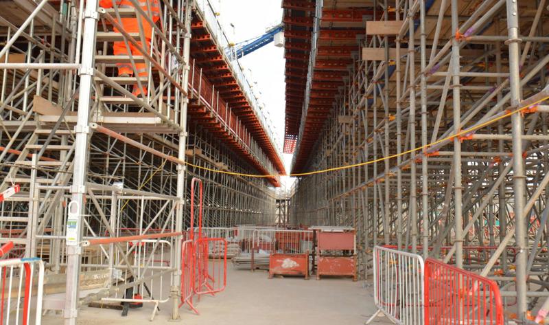
The techniques used for some of the bridges will be somewhat similar to those described so far. However, Curzon No. 3 Viaduct is unusual as it’s being constructed entirely in situ, rather than being assembled out of pre-manufactured elements.
In situ construction first involves assembling formwork on top of scaffold structure. Rebar (reinforcing bar) is then placed inside the formwork, before concrete is poured to form the structure for the deck.
This method was chosen due to the size and shape of the viaduct, which fans out from three tracks leading from Curzon No. 2 Viaduct to seven tracks which form the throat of Curzon Street station.
Work to build the first span appeared to progress relatively slowly, with construction of the span continuing through 2023 and only completed in April 2024.
However, construction of this first span closest to the station was complex, as it consisted of four individual spans, which together will be capable of supporting seven tracks.
Login to continue reading
Or register with RAIL to keep up-to-date with the latest news, insight and opinion.
More articles on:
Every Wednesday, RAIL Briefing brings you the most important stories, analysis of the biggest issues and critical scrutiny from leading industry experts which will put you at the heart of a successful British railway.
Registering and logging into the site also gives you access to gated content on the RAIL website.
SIGN UP NOW


, stands at Peterborough on April 8 2023. The ‘90’ has been acquired by Freightliner from DB Cargo. PIP DUNN.")


 on the Wast Coast Main Line on September 17 with the 1541 Jarrow Prax to Lindsey Oil Refinery Colas empty bogie tanks. PAUL BIGGS.")


Login to comment
Comments
No comments have been made yet.